EHS MANUAL
Spill Prevention Control & Countermeasure Plan
TABLE OF CONTENTS
Facility Owner & Operator Information
Facility Owner, Address, and Telephone
Facility Operator, Address, and Telephone
Facility Contact(s)
Product Storage
Waste Oil Storage
Miscellaneous Oil Storage
Drainage Pathway and Distance to Navigable Waters
Potential Spill Prediction, Volumes, Rates, and Control
Drainage control / Secondary Containment
Spill Control Equipment
Reporting and Spill Response Procedures
Truck Loading / Unloading Operations
Personnel Training and Spill Prevention Procedures
Facility Owner, Address, and Telephone:
Board of Curators of the University of Missouri
316 University Hall
Columbia, MO 65211
(573) 882-2388
Facility Operator, Address and Telephone:
Missouri University of Science and Technology
Rolla, MO 65409-0110
(573) 341-4122
Facility Contact(s):
Name: Mike Amick / Tony Hunt - Plan is currently being modified
Title: Physical Facilities Supervisor / Environmental Specialist
(573) 341-4305
The Missouri University of Science and Technology (Missouri S&T) is a public educational and research institution located in Rolla, Missouri approximately 100 miles west of St. Louis Missouri on Interstate 44 (See Figure 1). Missouri S&T receives products by common carrier via tank truck. Products are stored in above ground storage tanks (ASTs) located throughout the campus. Waste oils from routine vehicle and equipment maintenance, elevator hydraulic fluids, transformer oils, and oils associated with other processes (cooking oils, pump lubricating oils, etc..) are stored on campus as well.
This Facility has not experienced a spill event as defined by 40 CFR 112.2. This facility has not discharged more than 1000 gallons of oil into or upon the navigable waters of the United States or adjoining shorelines in a single spill event. This facility has not discharged more than 42 gallons of oil in each of two discharge events, as described in 40 CFR 112.4(a), into or upon navigable water of the United States or adjoining shorelines, reportable under Section 311(b) of the Federal Water Pollution Control Act (FWPCA), occurring within any twelve month period prior to January 1, 2001.
| Missouri S&T ID # | Location | Volume (Gallons) | Contents | Container Type |
| #1 | Mech. Eng. | 150 | Gasoline | Metal Tank |
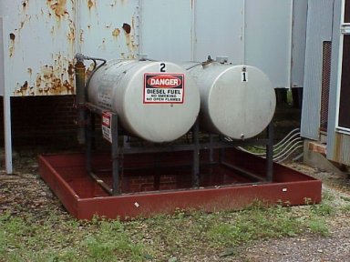
| #2 | Power Plant | 3000 | Diesel Fuel | Metal Tank |
| #3 | Parking Lot 7 | 250 | Gasoline | Metal Tank |
| #4 | Golf Course | 250 | Gasoline | Metal Tank |
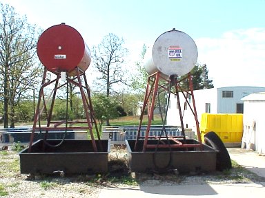
| #5 | Comp. Flow Lab | 2(130)=260 | Diesel Fuel | Metal Tank |
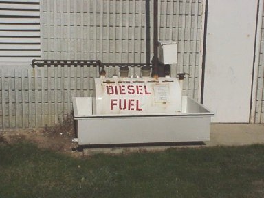
| #6 | General Services | 250 | Diesel Fuel | Metal Tank |
| #7 | General Services | 250 | Gasoline | Metal Tank |
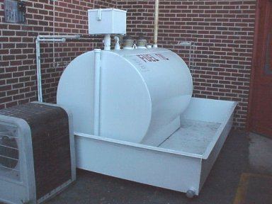
| #8 | T.J. Hall | 1500 | Fuel Oil | Metal Tank |
| #9 | T.J. Hall | 150 | Fuel Oil | Metal Tank |
| #10 | Miner Rec. | 500 | Fuel Oil | Metal Tank |
| #11 | Exp. Mine | 250 | Diesel Fuel | Metal Tank |
| Missouri S&T ID# | Location | Volume (Gallons) | Contents | Container Type |
| WO1 | Physical Facilities | (4)55=220 | Used Oil | 55 gallon drums in used oil container |
| WO2 | Power Plant | (4)55=220 | Used Oil | 55 gallon drums in used oil container |
Miscellaneous Oil Storage
Virgin oils used in general facility operations are stored in drums and containers of various sizes located throughout the campus. Transformer oils, associated with approximately 30 transformers, are located throughout the main campus. Hydraulic oil is also used for operation and control of elevators and other equipment on campus. Lubricating oils are located in several mechanical rooms for maintaining and servicing equipment.
DRAINAGE PATHWAY AND DISTANCE TO NAVIGABLE WATERS
The Mechanical Engineering Tank (Tank ID #1), Power Plant Tank (Tank ID #2), and the Power Plant Waste Oil Tank (Tank ID WO2) are located approximately one-half mile North of Love Branch and are equipped with secondary containment capable of containing entire contents of the tanks and sufficient freeboard for precipitation. A storm drain, which empties into Love Branch, is located on State Street approximately 150 feet from the tanks. The Mechanical Engineering Tank is located adjacent to the west wall of the Mechanical Engineering Building. The Power Plant Tank is located in the Southeast corner of the power plant, and the Waste Oil Tank is located about 25 feet south of the north smoke stack (See Figure 2). Any discharge from tanks #1 or #2 will flow to the south and southwest respectively, while flow from tank WO2 will flow to the east. Any flow from these tanks will eventually flow into the storm drain on State Street.
The Parking Lot 7 Tank (Tank ID #3) is located approximately one-half mile North of Love Branch and is equipped with secondary containment capable of containing entire contents of the tank and sufficient freeboard for precipitation. A storm drain, which empties into Love Branch, is located in Parking Lot 7 approximately 30 feet from the tank. Any Discharge from Tank 3 will flow to the south across the parking lot toward the storm drain (See Figure 3).
The Golf Course Tank (Tank ID #4) is located approximately one-half mile northwest of Love Branch and is equipped with secondary containment capable of containing entire contents of the tank and sufficient freeboard for precipitation. Surface drainage from this area flows to the southeast through ditches that discharge into Love Branch. Any discharge from Tank #4 will flow to the south until it reaches the drainage ditch approximately 150 feet from the tank (See Figure 4).
The Compressible Flow Lab Tank (Tank ID #5), consisting of two (2) 130 gallon metal tanks, is located approximately 1 mile north of Love Branch and is equipped with secondary containment capable of containing approximately 230 gallons. Drainage from this area flows to the south through ditches that discharge into Love Branch. Any discharge from Tank #5 will flow to southeast until it reaches a drainage ditch approximately 100 feet from the tank (See Figure 5).
The General Services Tanks (Tank ID's #6, 7,) are located approximately 1 mile north of Love Branch and are equipped with secondary containment capable of containing entire contents of the tanks and sufficient freeboard for precipitation. Drainage from these tanks flows to a storm drain, approximately 20 feet from the tanks, which discharges into tributaries of Love Branch (See Figure 6).
The Thomas Jefferson Hall Tank (Tank ID #8) is located approximately 3 miles south of Spring Creek and is equipped with secondary containment capable of containing entire contents of the tank and sufficient freeboard for precipitation. Drainage from the area flows to the north through surface drainage until entering tributaries of Spring Creek approximate 0.25 miles to the north (See Figure 7).
The Thomas Jefferson Hall Tank (Tank ID #9) is located approximately 3 miles south of Spring Creek and is equipped with secondary containment capable of containing entire contents of the tank and sufficient freeboard for precipitation. Drainage from this tank flows to the south into a storm drain which eventually discharges into Burgher Branch (See Figure 7).
The Miner Recreation Tank (Tank ID #10) is located approximately 1/2 mile north of Love Branch and is equipped with secondary containment capable of containing entire contents of the tank and sufficient freeboard for precipitation (See Figure 8). Drainage from this tank flows to the east into a storm drain which discharges into Love Branch.
The Experimental Mine Tank (Tank ID #11) is located adjacent to a tributary of Little Beaver Creek (See Figure 9) and is equipped with secondary containment capable of containing the entire contents of the tank and sufficient freeboard to precipitation. Any drainage from this tank will flow to the southeast to a tributary which eventually discharges into Little Beaver Creek.
POTENTIAL SPILL PREDICTIONS, VOLUMES, RATES AND CONTROL
| Source (Tank ID#) | Type of Failure | Volume (Gallons) | Rate (Gallons/Hr.) | Direction of Flow | Containment (Gallons) |
| #1 | Rupture: Leakage | 150 | 150 | South | 175 |
| #2 | Rupture: Leakage | 3000 | 3000 | East | 3205 |
| #3 | Rupture: Leakage | 250 | 250 | South | 360 |
| #4 | Rupture: Leakage | 250 | 250 | South | 360 |
| #5 | Rupture: Leakage | 260 (2 tanks) | 260 | Southwest | 230 |
| #6 | Rupture: Leakage | 250 | 250 | Southeast | 360 |
| #7 | Rupture: Leakage | 250 | 250 | Southeast | 360 |
| #8 | Rupture: Leakage | 1500 | 1500 | North | 2200 |
| #9 | Rupture: Leakage | 150 | 150 | East | 246 |
| #10 | Rupture: Leakage | 500 | 500 | Southeast | 655 |
| #11 | Rupture: Leakage | 250 | 250 | Southeast | 500 |
| WO1 | Rupture: Leakage | 220 | 220 | Southeast | 240 |
| WO2 | Rupture: Leakage | 220 | 220 | Southeast | 240 |
Catastrophic spillage from drums and containers stored indoors throughout the main campus could result in a maximum spill of approximately 100 to 200 gallons of hydraulic, vegetable, transformer, lubricating, mineral, or waste oils stored in any one location. Some of the rooms containing oils have floor drains including the boiler rooms, elevator service rooms, and the service garages. In the event of a release of oil in the vicinity of floor drains, the oil could pass through the storm-water system into surface waters. Containers and drums should be stored in secondary containment and inspected regularly for leaks or spills. Equipment and materials necessary to contain, prevent, and clean up spills should be available. Transformers should also be regularly inspected for leakage, and spill equipment should be available in case of transformer rupture. In the event of a spill or leak from drums, transformers, or elevators, spill control measures must be taken to insure that no oils reach navigable waterways through the use of spill control equipment and / or secondary containment.
Drainage control / Secondary Containment
Accumulation from all fuel storage tanks flows into catch basins located beneath the tanks. The basins are constructed as to hold the entire contents of the tanks plus and additional ten percent or more of the total volume to account for precipitation. The basins are drained via manual gate valves only after careful examination for any oil sheen has been conducted by qualified personnel. If water is clean, it is discharged through the gate valves. If petroleum products are present, or an oily sheen is observed, absorbent booms, pillows or mats are used to remove petroleum residues before discharging the contents of the basin. All absorbent materials used to clean petroleum products are properly disposed of in accordance with University policies, state and federal regulations.
Accumulation from Tank No. 2 flows into a concrete catch basin located beneath the tank. There is no drainage valve for this basin. In the event of a catastrophic failure or leakage from this tank, the catch basin will be drained using mechanical pumps and all oil contaminated materials will be collected and disposed.
Accumulation from Tank No. 5 flows into a steel catch basin located beneath the tanks. The basin is constructed as to hold approximately 230 gallons.
Spill control equipment, consisting of absorbent granules, waste containers, and hand tools, will be maintained at the physical facilities department to respond to leaks or spills from transformers, elevators, or other miscellaneous oil storage. Absorbent granules and other equipment is also available in vehicle maintenance shops and other areas where small quantities of oils are used and stored.
Spill Control Equipment
Spill control equipment such as absorbent pads, boom, pillows, or mats should be readily available at the Physical Facilities Department. At a minimum, there should be an adequate supply to respond to a spill of 30 gallons. Spill kits are commercially available which can provide the appropriate inventory of materials to have on hand and should be appropriate for the collection of oil.
REPORTING AND SPILL RESPONSE PROCEDURES
Upon observing a spill, personnel on the scene will take immediate steps to contain the spill if it is not contained by secondary containment structures or poses a safety risk. Spill control equipment, such as absorbent pads, booms, or granules, should be kept in the Physical facilities department and / or near storage areas where it can quickly be obtained and taken to a spill event. Personnel should prevent product from reaching drains, (e.g., floor drain or storm-water drain) using available spill control equipment, and then immediately call one of the 24-hour emergency telephone numbers below. Both phone numbers connect with personnel who will initiate the appropriate response and make the necessary regulatory contacts.
Monday through Friday 8 a.m.to 5 p.m.: (573) 341-4305
Outside the office hours: 911
The spill containment action may require the manual application of absorbent materials to prevent product from reaching drains or navigable waters. Site personnel are committed to performing spill prevention activities to support this plan unless an unsafe condition has been created by a spill. In the event that there is immediate danger to human health, site personnel will contact the Missouri University of Science and Technology police at 911.
When reporting a spill, the following information must be supplied:
(a) Name of Person Making Call
(b) Material and Quantity Involved
(c) Current Condition of Spill
(d) Health and/or Fire Hazard
(e) Building Location
(f) Location of Spill
(g) Telephone Number for Personnel Observing Scene
(h) Evacuation Details
(i) Reason / Cause of Spill
Any spill which causes a sheen or visible layer of oil on a U.S. navigable waterway must be reported verbally to the National Response Center 24-hour hotline at (800) 424-8802. This satisfies the requirement for notifying both the US EPA and the U.S. Coastguard. EHS personnel are responsible for making this notification.
As per 40 CFR Part 112.4, if the volume of the spill exceeds 1,000 gallons, or if two (2) oil spills occur within a 12-month period involving more than 42 gallons each, additional reporting procedures are required which will be performed by the EHS staff. Reporting requirements consist of submitting a report within sixty (60) days of the spill to the United States Environmental Protection Agency (EPA) Regional Administrator and the Missouri Department of Natural Resources (MoDNR). This report must describe the spill incident, the measures taken to mitigate / remediate the spill, and the mechanisms that have been or will be instituted to prevent a reoccurrence.
TRUCK LOADING / UNLOADING OPERATIONS
The University will stress the importance of following safe handling practices when delivering product to the various sites. Tank truck unloading procedures will meet the minimum requirements instituted by the United States Department of Transportation (US DOT). The fuel supplier will provide the systems necessary to prevent product from reaching streets, catch basins, or other drainage structures during product transfers. Such systems as absorbent material, drain covers, etc. will be provided by the fuel supplier. Prior to fueling, the fuel supplier will determine that the tank system to be filled is able to hold the volume of petroleum being delivered. The fuel truck operator will be present during delivery and take an active part in the prevention of spills. The fuel supplier will take immediate action to stop the flow of petroleum when the working capacity of the tank has been reached, or when an emergency or spill occurs. Prior to filling and departure of any tank truck, the lowermost drain and all outlets of such vehicles will be closely examined for leakage, and if necessary, tightened, adjusted, or replaced to prevent liquid leakage while in transit. An overfill occurring during tank truck unloading has the potential to reach the municipal storm sewers. In the event of a spill, the storm sewers located in the flow path will be protected by immediately placing absorbent booms or covers in these areas.
INSPECTIONS AND RECORDING KEEPING
As part of the SPCC Plan, inspection of the facility and training of facility personnel will be performed by the University. Records of the inspections, signed by the appropriate supervisor or inspector, will be made part of the SPCC Plan and maintained for a period of three (3) years.
The SPCC Plan will be reviewed and evaluated every five (5) years. If technical amendments are required as a result of the review, the SPCC Plan will be amended within six (6) months and re-certified by a Professional Engineer.
Implementation of amendments is required within six (6) months of amendment. Non-technical amendments such as changes to phone numbers, names, etc., will not require re-certification (40 CFR 112.5.(C)).
A representative of the Physical Facilities Department will inspect the AST facilities on a monthly basis and will retain inspection reports at the Physical Facilities Department. Inspection reports will include those recommendations necessary to comply with SPCC requirements. The inspection reports for the past year for the storage tanks will be attached to the SPCC plan. The inspections will focus on potential spill sources such as AST containers, tank supports and foundations, secondary containment, fuel unloading areas, petroleum product piping, valves, pumps, grounding equipment, fire extinguishers, and suppression systems where applicable.
Any visible oil leaks sufficiently large to cause the accumulation of oil in diked areas or secondary containment basins will be promptly corrected. In addition, a complete record of any spills that occur will be maintained at the facility. Tank integrity inspections shall also be performed on a regularly scheduled basis. These integrity inspections shall combine visual inspections with non-destructive testing methods such as hydrostatic testing, radiographic testing, ultrasonic testing, acoustic emissions testing, or other non-destructive shell testing (40 CFR 112.7 (e)(2)(iii)(iv)). Records of inspections and tests kept pursuant to usual and customary business practices are sufficient for purposes or the rule.
As a general rule, the University must take the following measures that are necessary to comply with the SPCC requirements.
- At a minimum, monthly visual observation of the fuel system and storage areas is required to check for leaks and spills.
- Check the condition of floor, slab, walls and any secondary containment structures for cracks, holes, or other areas of potential leaks on a monthly basis and file inspections for the current year with the SPCC plan. Immediately repair and seal any problem areas in secondary containment structures.
- Check valves that may permit direct outward flow of the AST's content to the vault floor to ensure that they are securely locked in the closed position.
- Inspect contents of secondary containment basins for oily sheen prior to discharging contents after precipitation events (40 CFR 112.7(e)(2)(iii)(B-D)). Drainage of rainwater from secondary containment structures will be acceptable if:
-
- The bypass valve is normally closed.
- Inspection for the run-off rain water ensures compliance with applicable water quality standards and will not cause a harmful discharge as defined in 40 CFR 110.
- The bypass valve is opened, and resealed following drainage under responsible supervision. The employee discharging the water of the secondary containment structure will remain onsite until all water is drained and reseal the valve after draiing the structure.
- Adequate records are kept of such events which include names responsible personnel, date, Tank ID, and condition of contents of basin (i.e. whether or not there was oil sheen present and any methods used to absorb oily materials prior to discharge).
- If an oily sheen is observed, the inspector will insure that petroleum product is removed and properly disposed of prior to discharging water from the basin.
-
- Provide training to all university personnel who will perform inspections. Training will include inspection, reporting, and spill response procedures. Copies of training records will be kept with the SPCC program. Training will be required for all personnel with annual refresher training thereafter.
- Perform regularly scheduled tank integrity testing on AST's. Such an inventory may include:
-
- Rolls and pads of absorbent materials
- Granular absorbent material
- Shovels, boots, gloves and eye protection
-
- Master flow and drain valves and any other valves that will permit the direct outward flow of the tanks contents to the surface should be securely locked in the closed position when in non-operating or non-standby status.
- Facility lighting should be commensurate with with the type and location of the facility. Consideration should be given to the following:
-
- Discovery of spills occurring during hours of darkness by operating personnel, general public, or local police, etc.
- Prevention of spills through acts of vandalism.
-
PERSONNEL TRAINING AND SPILL PREVENTION PROCEDURES
All oil handling personnel responsible for identified tanks should be trained in the operation and maintenance of equipment to prevent or contain oil discharges and also in applicable pollution control laws, rules, and regulations. A record summary of the training sessions will be maintained at the facility. Additionally, discharge prevention briefings shall be conducted at least once per year to assure adequate understanding of the SPCC plan. These briefings must highlight and describe known discharges as described in 40 CFR 112.1(b), or failures, malfunctioning components, and recently developed precautionary measures.
Missouri University of Science and Technology Police (573) 341-4300
Environmental Health and Safety Dept (573) 341-4305
Rolla Police Dept. (573) 364-1213
Rolla Fire Dept. (573) 364-3989
Waste Contractor (PCI) (219) 397-3951
Department of Natural Resources (573) 634-2436
National Response Center 24-hour hotline (800) 424-8802
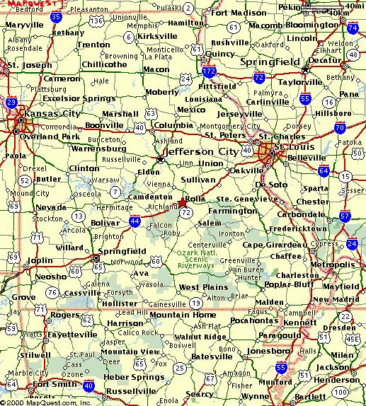 : Map Showing Location of Rolla, Mo.
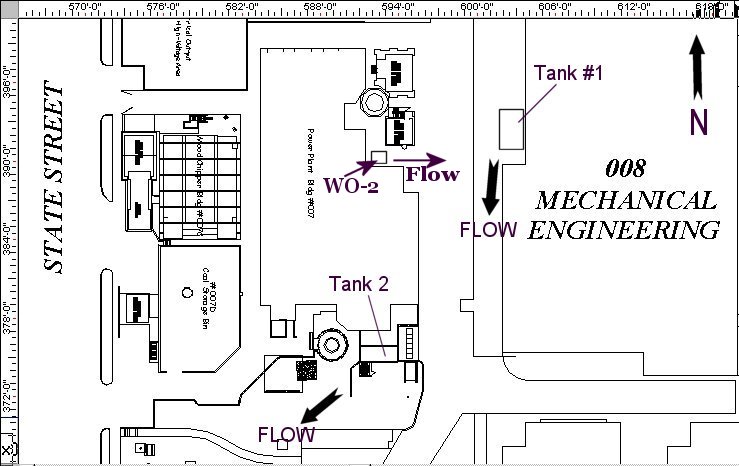 : Map showing locations of Tanks #1, #2, & WO2.
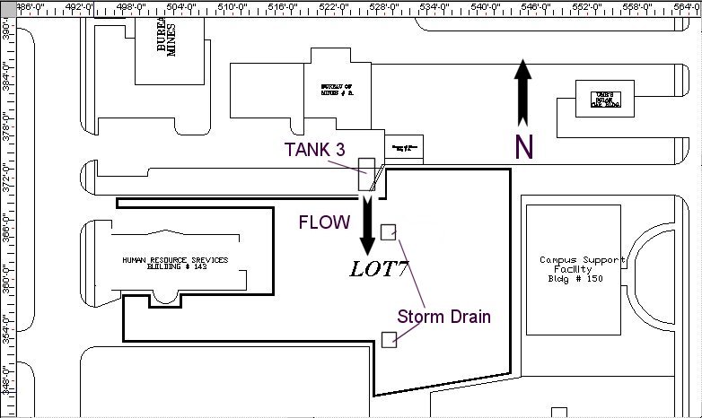 : Map showing location of Tank #3.
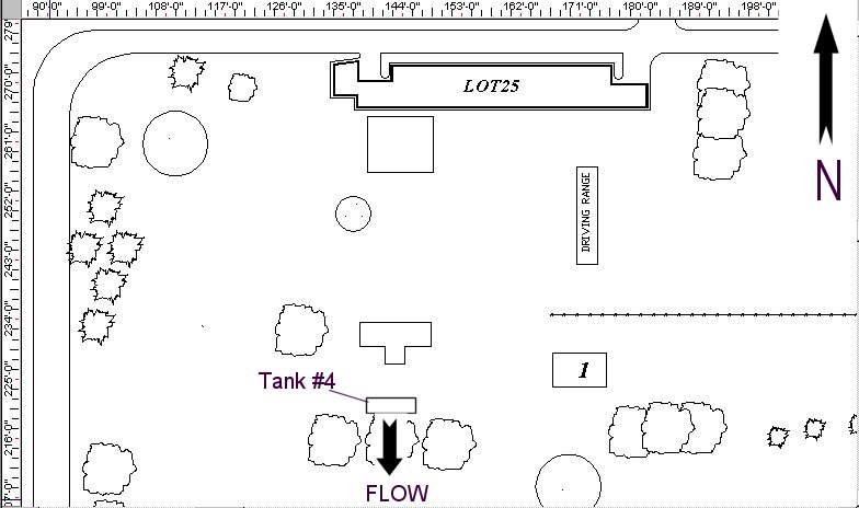 : Map showing location of Tank #4.
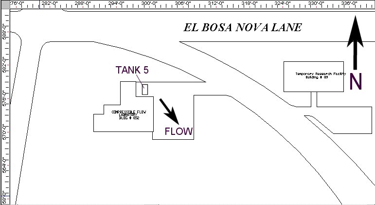 : Map showing location of Tank #5.
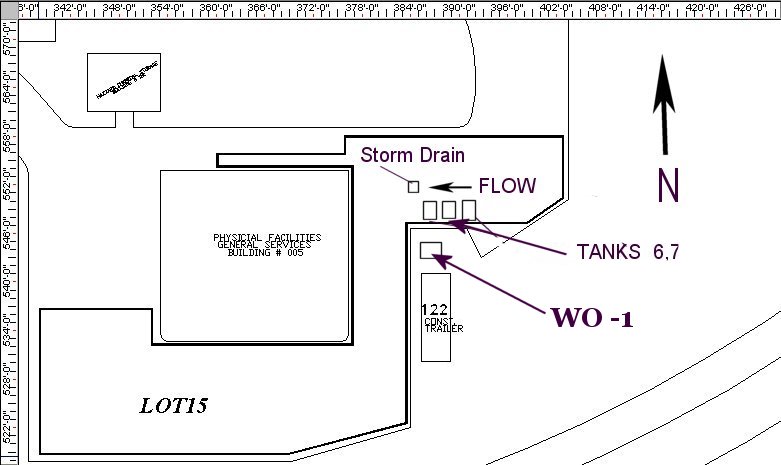 : Map showing location of Tanks #6 , #7, & WO1.
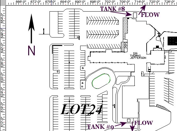 : Map showing location of Tanks #8 & #9.
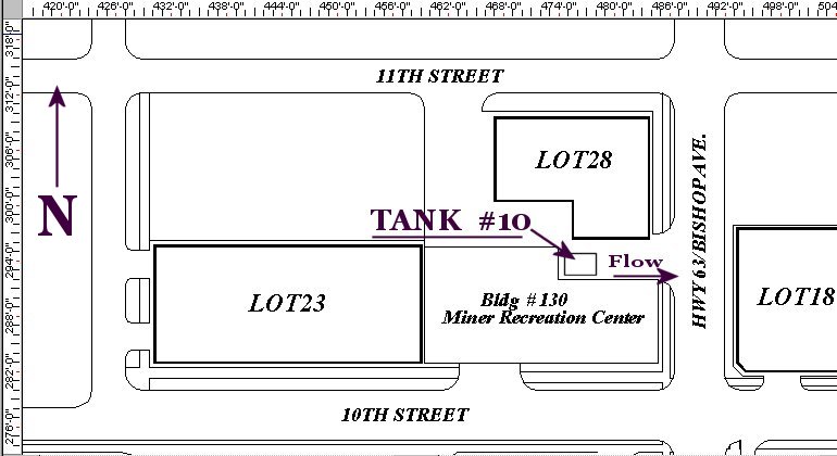 : Map showing location of Tank #10
Figure 9: Map showing location of Tank #11
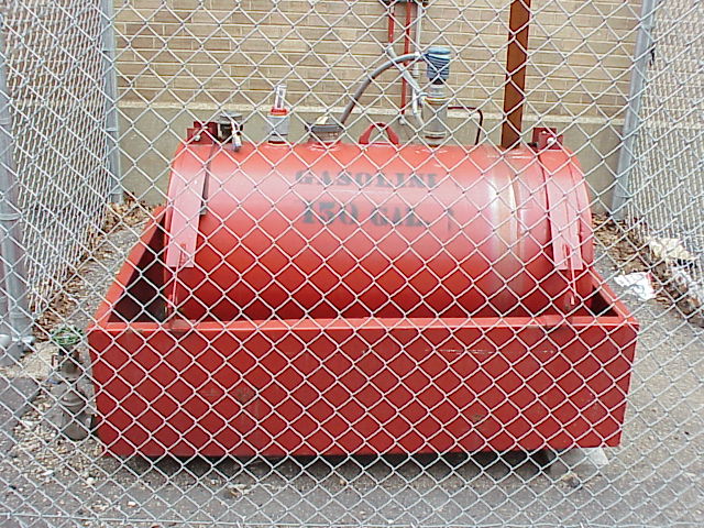 M echanical Engineering Tank (Tank ID #1) Facing East.
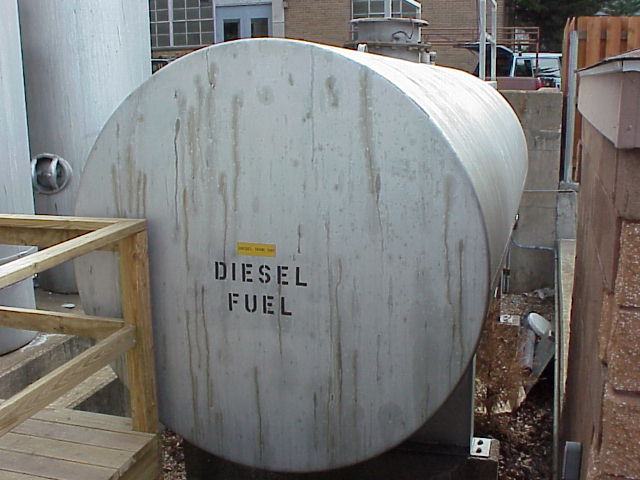 : Power Plant Tank (Tank ID #2) Facing Southwest.
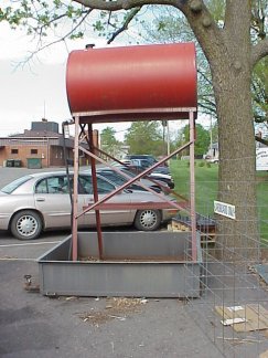 : Parking Lot 7 (Tank ID #3) Facing West.
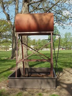 : Golf Course Tank (Tank ID #4) Facing West.
 : Compressible Flow Lab (Tank ID #5) Facing West.
 : General Services (Tank ID's #6 & #7) Facing South.
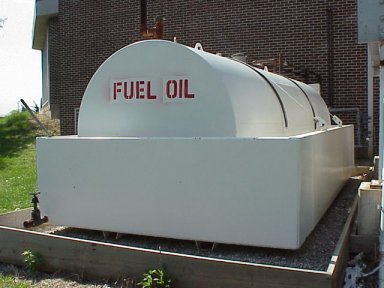 : Thomas Jefferson Hall (Tank ID #8) Facing South.
 : Thomas Jefferson Hall (Tank ID #9) Facing North.
 Miner Recreation (Tank ID #10) Facing South.
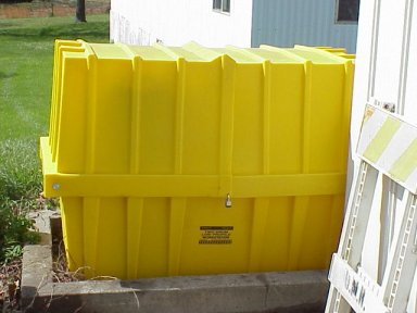 : Physical Facilities Waste Oil Container (Tank ID WO1) Facing South.
 : Power Plant Waste Oil Container (Tank ID WO2) Facing West.
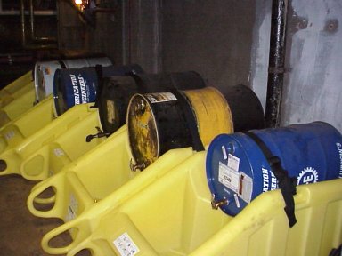
Photo 13: Experimental Mine (Tank ID #11) Facing South.
Revision Date: August 23, 2011